4. Installation
Warning
This product may only be installed by a qualified electrical engineer.
4.1. Location
The product must be installed in a dry and well-ventilated area, as close as possible to the batteries.
The product must be installed in a manner that ensures it is not expected to come into contact with persons under normal conditions.
The inverter/charger is suitable for wall mounting. A solid surface, suitable for the weight and dimensions of the product must be available (e.g., concrete, or masonry). For mounting purposes, a hook and two holes are provided at the back of the casing (see appendix G).
Warning
The interior of the product must remain accessible after installation.
Try and keep the distance between the product and the battery to a minimum in order to minimize cable losses.
Warning
For safety reasons, this product should be installed in a cool environment. Do not store or place any flammable materials (such as chemicals, curtains, textiles, synthetic items, or other combustibles) in the immediate vicinity of the installation.
Warning
Every system installation must include a way to disconnect the AC and DC circuits. Circuit breakers used for overcurrent protection can also serve as disconnects. When fuses are used, separate disconnect switches are required between the source and the fuses.
Warning
WARNING - BATTERIES CAN PRESENT A RISK OF ELECTRIC SHOCK, BURNS FROM HIGH SHORT-CIRCUIT CURRENTS, FIRE, OR EXPLOSION FROM VENTED GASSES.
Replace batteries with the same number and type.
Refer to you local codes for proper battery disposal requirements.
Warning
WARNING – RISK OF EXPLOSIVE GASES. WORKING IN THE VICINITY OF A LEAD-ACID BATTERY IS HAZARDOUS. LEAD-ACID BATTERIES GENERATE EXPLOSIVE GASES DURING NORMAL OPERATION.
Please observe the following precautions when working in the vicinity of a lead-acid battery.
PERSONAL SAFETY PRECAUTIONS:
Never work alone near a lead-acid battery. Ensure someone is close-by to assist you in case of an emergency.
Ensure first aid and eye wash equipment is readily available before working on or near the battery.
Wear safety goggles or a face shield and protective clothing. Avoid touching your eyes while working near a battery.
If battery acid contacts skin or clothing, wash immediately with soap and water. If acid enters your eye, immediately flush the eye with cold running water for at least 10 minutes and seek medical attention right away.
NEVER smoke or allow sparks or open flames within the vicinity of a battery or engine.
Use insulated tools when working on the battery. Be extremely careful not to drop metal tools or objects onto the battery. A dropped metal tool can create sparks or cause a short circuit, which may result in an explosion or fire.
Remove metal jewelry and watches when working with a lead-acid battery. A lead-acid battery can produce a short-circuit current high enough to melt or weld a ring or similar metal object to metal, causing severe burns.
NEVER charge a frozen battery.
If removing the battery from a vehicle or vessel, always remove grounded terminal from the battery first. Switch off all circuits before connecting or disconnecting the battery terminals to prevent arcing.
Ensure the battery is installed in a well ventilated space.
Keep the battery terminals clean and free of corrosion. Prevent corrosion material from coming in contact with eyes.
Always follow the battery manufacturer’s specific precautions and instructions. This includes whether or not to remove the cell caps while charging and observe the recommended charging rates.
Warning
MARINE UNIT LOCATION
Locate marine unit away from battery in a separate, well ventilated compartment
Never place marine unit directly above the battery; corrosive battery gases will damage it.
Never allow battery acid to drip onto the marine unit when reading gravity or filling the battery.
Do not operate the marine unit in a closed-in area or restrict ventilation in any way.
Warning
DC CONNECTION PRECAUTIONS
Connect and disconnect DC output connections only after setting any marine unit switches to off position. Disconnect AC cords from electric outlets or open AC disconnect switches.
Warning
EXTERNAL CONNECTIONS SHALL COMPLY WITH THE UNITED STATES COAST GUARD ELECTRICAL REGULATIONS (33CFR183, SUB PART I).
Warning
GROUNDING INSTRUCTIONS – A marine unit should be connected to a grounded, metal, permanent wiring system; or an equipment-grounding conductor should be run with circuit conductors and connected to equipment-grounding terminal or lead on unit. Connections to the unit should comply with all local codes and ordinances.
Warning
This product is not suitable for direct connection to a vehicle's electrical system. It should be connected to a DC system that includes its own dedicated service or house battery with appropriate fusing, and DC wiring gauge. For recommendations on battery capacity, fuse rating, and cable gauge, refer to Chapter Connection of battery cables in this manual."
4.2. Vibration management
Caution
CAUTION
When integrating inverter/chargers with generators in a single enclosure (hybrid generators), using shock mounts is mandatory. They mitigate damage risk to the inverter/charger by absorbing the generator's operational energy, thus extending component lifespan.
Key criteria for selecting shock mounts include:
Selection is based on the specific generator vibration frequency ranges to be isolated.
The shock mounts must bear the equipment's weight without impairing functionality.
4.3. Connection of battery cables
To fully utilize the product's capacity, ensure the use of batteries with adequate capacity, an appropriate DC fuse, and battery cables of sufficient cross-section. DC cables should be copper, with a 90ºC (194ºF) rating. Refer to the table below for sizing recommendations.
In Canada, battery installation should be in accordance with the storage battery rules of the Canadian Electrical Code, Part I.
A battery disconnection mechanism must be included as part of the installation. It should be capable of being connected to the DC terminals and must be rated for at least the DC fuse current requirements specified in the table below:
Model | Battery capacity | DC fuse | Cross-section per positive and negative terminal connection for cables between 0 and 5m *, **, *** | Cross-section per positive and negative terminal connection for cables between 5 and 10m *, **, *** |
|---|---|---|---|---|
12/3000/120 | 400 - 1200Ah | 400A | 2x AWG 1/0 | 2x AWG 2/0 |
12/4k/160 | 400 - 1200Ah | 600A | 2x AWG 2/0 | 2x AWG 4/0 |
24/3000/70 | 200 - 700Ah | 300A | AWG 1/0 | 2x AWG 1/0 |
48/3000/35 | 100 - 400Ah | 125A | AWG 1 | AWG 2/0 |
24/5000/120 | 400 - 1200Ah | 400A | 2x AWG 1/0 | 2x AWG 2/0 |
48/5000/70 | 200 - 800Ah | 200A | AWG 2/0 | AWG 4/0 |
* Follow local installation rules.
** Do not locate battery cables in a closed conduit
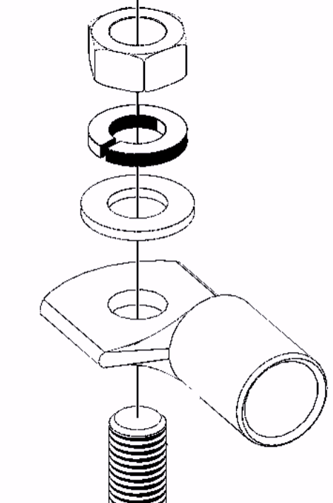
Connection procedure WarningUse a torque wrench with an insulated box spanner in order to avoid shorting the battery. Recommended torque: 12 Nm (M8 nut) Avoid shorting the battery cables. | ||
Proceed as follows to connect the battery cables:
|
| |
Notice
Internal resistance is an important factor when working with low-capacity batteries. Please consult your supplier or the relevant sections of our Energy Unlimited or Wiring Unlimited books. Both can be downloaded from our website.
4.4. Connection of the AC cabling
Warning
This is a safety class I product (supplied with a ground terminal for safety purposes). Its AC input and/or output terminals and/or grounding point on the outside of the product must be provided with an uninterruptible grounding point for safety purposes.
This product is provided with a ground relay (relay H, see appendix B) that automatically connects the Neutral output to the chassis if no external AC supply is available. If an external AC supply is provided, the ground relay H will open before the input safety relay closes. This ensures the correct operation of an earth leakage circuit breaker connected to the output.
In a fixed installation, an uninterruptable grounding can be secured by means of the grounding wire of the AC input. Otherwise, the casing must be grounded.
In a mobile installation (for example, with a shore current plug), interrupting the shore connection will simultaneously disconnect the grounding connection. In that case, the casing must be connected to the chassis (of the vehicle) or to the hull or grounding plate (of the boat).
The inverter incorporates a mains frequency isolating transformer. This precludes the possibility of DC current at any AC port. Therefore, type A RCDs can be used.
In case of a boat, direct connection to the shore ground is not recommended because of potential galvanic corrosion. The solution to this is using an isolation transformer.
Warning
This unit or system is provided with fixed trip limits and shall not be aggregated above 30kW on a single point of common connection.
The AC terminal blocks can be found on the printed circuit board, see Appendix A.
Do not invert neutral and phase when connecting the AC.
The AC connections need to be made with three-wire 90ºC (194ºF) copper cable.
MultiPlus-II 120V - 3k and 4k models | AC-in | AC-out-1 | AC-Out-2 |
|---|---|---|---|
Note that AC-in and AC-out-1 have an M40 cable gland, and AC-out-2 has an M32 cable gland. | |||
Rated current | 50 A | 50 A | 32 A |
Recommend fuse or circuit breaker | 50 A | 50 A | 32 A |
Minimum wire gauge | AWG 6 | AWG 6 | AWG 10 |
Ferrule pin and stripping length | 0.7 inch (18 mm) | 0.7 inch (18 mm) | 0.7 inch (18 mm) |
MultiPlus-II 120V - 5k models | AC-in | AC-out-1 | AC-Out-2 |
|---|---|---|---|
Rated current | 95 A | 115 A | 48 A |
Recommend fuse or circuit breaker | 95 A | 115 A | 48 A |
Minimum wire gauge | AWG 4 | AWG 2 | AWG 4 |
Ferrule pin and stripping length | 0.7 inch (18 mm) | 0.7 inch (18 mm) | 0.7 inch (18 mm) |
AC-in (Maximum Torque: 2 Nm)
The AC input cable can be connected to the terminal block ‘AC–in’.
From left to right: “N” (neutral), “PE” (earth) and “L” (phase)
The AC input must be protected by a fuse or magnetic circuit breaker rated at 50A (for 3kVA model) and 95A (for 5kVA model) or less, and the cable cross-section must be sized accordingly. If the input AC supply is rated at a lower value, the fuse or magnetic circuit breaker should be downsized accordingly. If the input AC supply is rated at a lower value, the fuse or magnetic circuit breaker should be downsized accordingly.
AC-out-1 (Maximum Torque: 2 Nm)
The AC output cable can be connected directly to the terminal block ‘AC-out’.
From left to right: “N” (neutral), “PE” (earth) and “L” (phase)
With its PowerAssist feature the inverter/charger can add up to 3 kVA (that is 3000 / 120 = 25 A) to the output during periods of peak power requirement. Together with a maximum input current of 50 A, the output can supply up to 50 + 25 = 75 A. On the 48/3000/35-50 unit, AC-out-1 is limited to 50A. A UL 943 compliant residual current circuit breaker (RCCD) and fuse or circuit breaker rated to support the expected load must be included in series with the output, and the cable cross-section must be sized accordingly.
And for the 5kVA model the inverter/charger can add up to 5 kVA (that is 5000 / 120 = 42 A) to the output during periods of peak power requirement. Together with a maximum input current of 95 A, the output can supply up to 95 + 42 = 137 A. A UL 943 compliant residual current circuit breaker (RCCD) and fuse or circuit breaker rated to support the expected load must be included in series with the output, and the cable cross-section must be sized accordingly.
AC-out-2 (Maximum Torque: 2 Nm)
A second output is available that disconnects its load in the event of battery operation. On these terminals, equipment is connected that may only operate if AC voltage is available on AC-in-1, e.g. an electric boiler or an air conditioner. The load on AC-out-2 is disconnected immediately when the inverter/charger switches to battery operation. After AC power becomes available on AC-in-1, the load on AC-out-2 will be reconnected with a delay of approximately 2 minutes. This to allow a genset to stabilise.
A UL 943 compliant residual current circuit breaker (RCCD) and fuse or circuit breaker rated at max. 32A must be connected in series with AC-out-2.
4.5. Optional Connections
A number of optional connections are possible:
4.5.1. Remote Control
The product can be remotely controlled in two ways.
With an external switch connected to the "Remote on/off connector" terminal (see Appendix A). Operates only if the switch on the inverter/charger is set to “on”.
With a Digital Multi Control panel connected to one of the two VE.Bus RJ45 sockets (see Appendix A). Operates only if the switch on the inverter/charger is set to “on”.
See Appendix A for the location of the connector.
4.5.2. Programmable relay
The product is equipped with a programmable relay.
The relay can be programmed for all kinds of other applications however, for example as a starter relay for a generator.
See Appendix A for the location of the connector.
4.5.3. Programmable I/O ports
The product is equipped with 2 analogue/digital input/output ports.
These ports can be used for several purposes. One application is communication with the BMS of a lithium-ion battery.
See Appendix A for the location of the connector.
4.5.4. Starter battery
The 12 and 24V models have a connection for charging a starter battery. Output current is limited to 4A.
See Appendix A for the location of the connector.
4.5.5. Voltage sense
For compensating possible cable losses during charging, two sense wires can be connected with which the voltage directly on the battery or on the positive and negative distribution points can be measured. Use wire with a cross-section of 0.75mm² (AWG 18).
During battery charging, the inverter/charger will compensate the voltage drop over the DC cables up to a maximum of 1 Volt (i.e. 1V over the positive connection and 1V over the negative connection). If the voltage drop threatens to become larger than 1V, the charging current is limited in such a way that the voltage drop remains limited to 1V.
See Appendix A for the location of the connector.
4.5.6. Temperature sensor
For temperature-compensated charging, a temperature sensor can be connected. The sensor is isolated and must be fitted to the negative terminal of the battery.
Note
The temperature sensor is not supplied with 48V models.
It can be ordered separately. Order number: ASS000001000
See Appendix A for the location of the connector.
4.5.7. Parallel connection
Up to six identical units, can be connected in parallel. When connecting inverter/charger units in parallel, the following requirements must be met:
All units must be connected to the same battery.
A maximum of six units can be connected in parallel.
Only identical devices may be connected in parallel.
The DC connection cables to the devices must be of equal length and cross-section.
If a positive and a negative DC distribution point is used, the cross-section of the connection between the batteries and the DC distribution point must at least equal the sum of the required cross-sections of the connections between the distribution point and the inverter/charger units.
Place the inverter/charger units close to each other, but allow at least 10cm for ventilation purposes under, above and beside the units.
UTP cables must be connected directly from one unit to another (and to the remote panel). Connection or splitter boxes are not permitted.
Always interconnect the negative battery cables before placing the UTP cables.
Only one remote control means (panel or switch) can be connected to the system.
4.5.8. Three-phase connection
The inverter/charger can also be used in a 3-phase wye (Y) configuration. To this end, the devices are connected by means of standard RJ45 UTP cables (the same as for parallel operation). The system of inverter/chargers (and the optional Digital Multi Control panel) will require subsequent configuration (see the Configuration chapter.
For prerequisites, see the Parallel connection chapter.
Notice
The inverter/charger is unsuitable for a three-phase delta (Δ) configuration.
Strings of paralleled units can be connected in three phases.